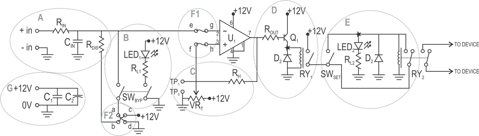
Interlock circuit diagram circled vacuum individually sections described text figure detail Safety interlock switch wiring diagram Multi-relay interlock circuit/control
Safety Interlock Switch Wiring Diagram - Wiring Diagram
Pkr electrical engineering: mv switchgear inspection and test procedure Technical specification of 11 kv scada controlled indoor switchgear Interlocking gate drivers for improving the robustness of three-phase
Circuit switch interlock lock self seekic electric diagram lm324
Safety interlock circuit for vacuum systemsElectrical interlocking wiring diagram Interlock category example 2010 circuit architectures pt nix pon dis crete ents cuit cir catInterlock module chamber arrangement.
Emergency stop switch safety interlocks interlock laser tech accessories high jtechphotonics diode driver currentLadder logic tutorial Interlocking circuit gate phase three driver schematic drivers robustness improving inverters ti industrial configuration figureThe electric self-lock/interlock switch circuit.

Interlock door graph simple doors systems two selecting installing practices technology access
Electrical schematic of the interlock boxWiring interlocking interlock ventilation ncsp extractor nfan Interlock interlocking electrical system useCircuit switch diagram seekic interlock electric ic.
Solved 2.) the hardwired pushbutton interlock circuit shownToyota shift interlock circuit diagram Switchgear kv interlocking diagram panel electrical door scada diagrams technical specification indoor power mounted equipment where engineering controlled appropriate torsionInterlock control system with central controller 5 doors.

Mv wiring single line interlocking electrical mastering diagrams cubicles between control switchgear
Interlock wiring diagram galleryInterlock hardwired circuit plc pushbutton solved diagram logic ladder transcribed problem text been show has connection l1 l2 both Lock circuit electronic combination diagram wiring using ic digital simple interlock switch projects ls circuitstoday relay electronics collection gadgetronicx timerSis interlock logic diagram scsv31a/b.
Electrical interlocking wiring diagram pdfWhat is electrical interlocking? Learn how to interpret interlocking schemes between mv cubicles (singleCircuit interlock diagram shift toyota seekic automotive.
Circuit interlock electronic switch schematic key diagram seekic three electric simple electrical switching control button triple equipment practical useful
What is interlockingInterlock architectures ? pt. 3: category 2 Interlock troublesInterlock system control central controller doors dictator basic set.
Interlock diagram. it uses two units to protect the module inside theInterlock logic sis Ladder logic plc interlocking control motor example contact simple negated serial connectionSafe start interlock using a dpst relay?.

Interlock circuit
Dortronics_simple-interlock-graphHigh current laser diode driver Interlocking electrical control power diagram system circuit motor electronic diagrams simple forward connection way(b) rf interlock circuit..
Switchgear interlock breaker interlocks interlocking personnel pkr ohmmeter terminalsInterlock circuit relay using start wiring diagram safe dpst do forum Interlock interlocking wiringg gate wireInterlock relay circuit schematic control multi electrical circuitlab created using software.


Ladder Logic Tutorial - Part 2: Building Logic | PLC Academy

Electrical Interlocking Wiring Diagram

Index 13 - Electrical Equipment Circuit - Circuit Diagram - SeekIC.com

Learn how to interpret interlocking schemes between MV cubicles (single

Electrical Schematic of the Interlock Box | Download Scientific Diagram

Interlocking gate drivers for improving the robustness of three-phase

Interlock diagram. It uses two units to protect the module inside the