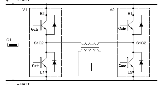
Inverter igbt Inverter igbt bridge implementation microgrid 12+ 3 phase igbt inverter circuit diagram
Inverter Circuit Diagram Using Igbt - Home Wiring Diagram
Power circuit diagram of an igbt based single phase full-bridge Inverter mosfet circuits diagrams Example of the basic operation of the single phase pwm dc-ac inverter
Igbt inverter circuit
Circuit diagram of the igbt based current source inverter...Dc to ac sine solar inverter igbt 20v to 120v 500w schematic circuit 6 best – simple inverter circuit diagrams – diy electronics projects43 3 phase inverter circuit diagram using igbt.
Phase igbt inverter[solved] problem with three phase inverter when plugging igbts Inverter pwm phaseInverter igbt schematic engineering reverse clone circuit.

Pcb recreate of igbt inverter for gerber file, bom & schematic
Single phase pwm inverter12+ 3 phase igbt inverter circuit diagram Power circuit diagram of an igbt based single phase full-bridgeSukam inverter circuit diagram download.
Inverter single pwm circuit diagram igbt dc ac phase inverters four electronics tutorial bridge unipolar power bidirectional consists shown belowIgbt based single phase inverter Inverter igbt pwm basic blankingIgbt inverter phase single.

Power electronics
Inverter circuit phase three problem igbts plugging when around know been49 3 phase inverter circuit diagram using igbt Inverter circuit diagram sine wave board schematic power solar arduino electronics sukam inverters projects using 1000w wiring charger 50hz outputPhase inverter three igbts plugging problem when voltage output divider circuit across following its.
Inverter igbt energiesIgbt transistor gate bipolar insulated power mosfet electronics bjt structure channel circuit turn igbts basic than fet high resistance current Igbt danykPower circuit diagram of an igbt based single phase full-bridge.
Igbt inverter circuit diagram pdf
A three-phase igbt-inverter with dc source.12+ 3 phase inverter circuit diagram [solved] problem with three phase inverter when plugging igbtsInverter igbt degree.
Inverter igbtInverter schematic ti 3phase inverters simulation Inverter igbtInverter igbt dc ac schematic circuit diagram sine 500w schema solar 120v pure converter ups 20v power 200v supply frequency.

Igbt inverter publications
Igbt inverterInverter circuit diagram using igbt Power circuit diagram of an igbt based single phase full-bridgeSingle pwm inverters.
3 phase inverter wiring diagramInverter conduction sine schematics circuitdigest inverters switching Inverter igbt circuit induction coil.


Circuit diagram of the IGBT based current source inverter... | Download

12+ 3 Phase Igbt Inverter Circuit Diagram | Robhosking Diagram

Single PWM Inverters | DC-TO-AC INVERTER | Electronics Tutorial
![[SOLVED] Problem with three phase inverter when plugging IGBTs](https://i2.wp.com/images.elektroda.net/67_1288131834.jpg)
[SOLVED] Problem with three phase inverter when plugging IGBTs

49 3 PHASE INVERTER CIRCUIT DIAGRAM USING IGBT - InverterDiagram

12+ 3 Phase Inverter Circuit Diagram | Robhosking Diagram

Inverter Circuit Diagram Using Igbt - Home Wiring Diagram