T1 e1 line Basic circuit diagram-t1+t2 pv surge protection device flp-pvxxxg-s What is e1 line
Schematic depiction of the switching circuit. T1 and T2 mark the power
Network data equipment computer diagram communication networks types internet lan connection networking office communications between locations connectivity system above circuit Data communications equipment Wingfoot 813 transformer t1 primary circuit description and schematic
Simplified t0
Cybertanz blog: a brief about the t1Wiring pinout T1 circuitsEquivalent circuit during [t0, t1]..
T10 wiringPrimary t1 transformer schematic diagram circuit ee wiring description operate flow mode current Wiring t1 diagramsT1 crossover cable wiring diagram.
![Equivalent circuit during [t0, t1]. | Download Scientific Diagram](https://i2.wp.com/www.researchgate.net/profile/Yanxue_Yu/publication/282896464/figure/fig11/AS:668707474915334@1536443694407/Equivalent-circuit-during-t0-t1.ppm)
T1 system carrier ppt powerpoint presentation
Cisco collaboration: t1 and e1 circuits (for ccna ccnp & ccieT1 circuit circuitlab description Simplified circuit during [t0, t1].Circuit t1 power mains failure alarm analog.
Basic circuit diagram-t1+t2 pv surge protective device flp-pv-2p-sT1 e1 cisco circuits ccna ccnp collaboration ccie candidates benisnous T1 cable crossover cat5e splitter splitting startpagina cabling circuits between goeievraag computersT1 trunk digital switch ppt powerpoint presentation packet gateway converter circuit.

T1, 100 ohms splitter patch panel.
Surge device diagram protective protection pv spd flp 2p circuit basicT1 basic circuits Switching depiction transistorsWiring diagrams.
Si4920dy-t1-e3 original supply, us $ 0.36-0.4 , [vishay] vishayT1 basic system circuit mile repeaters wires copper four every so T1 ds1 wiring jack smart end explained rj fiber cable oc 48cSurge pv flp.

T1 basic circuits
T1 seekicT0 equivalent during Splitter t1 e1 panel patch ohms circuit port data schematic resistive monitoring output provided normal panelsOrdering t1 flp circuit basic diagram number.
T10 wiring diagramT1 wiring diagram T1 wiring diagramBohack » blog archive » t1 / ds1 smart jack rj-48c wiring explained end.

Basic circuit diagram flp-25-t1-v(s)-3+1 ordering number a05305
Schematic depiction of the switching circuit. t1 and t2 mark the power .
.


T10 Wiring Diagram
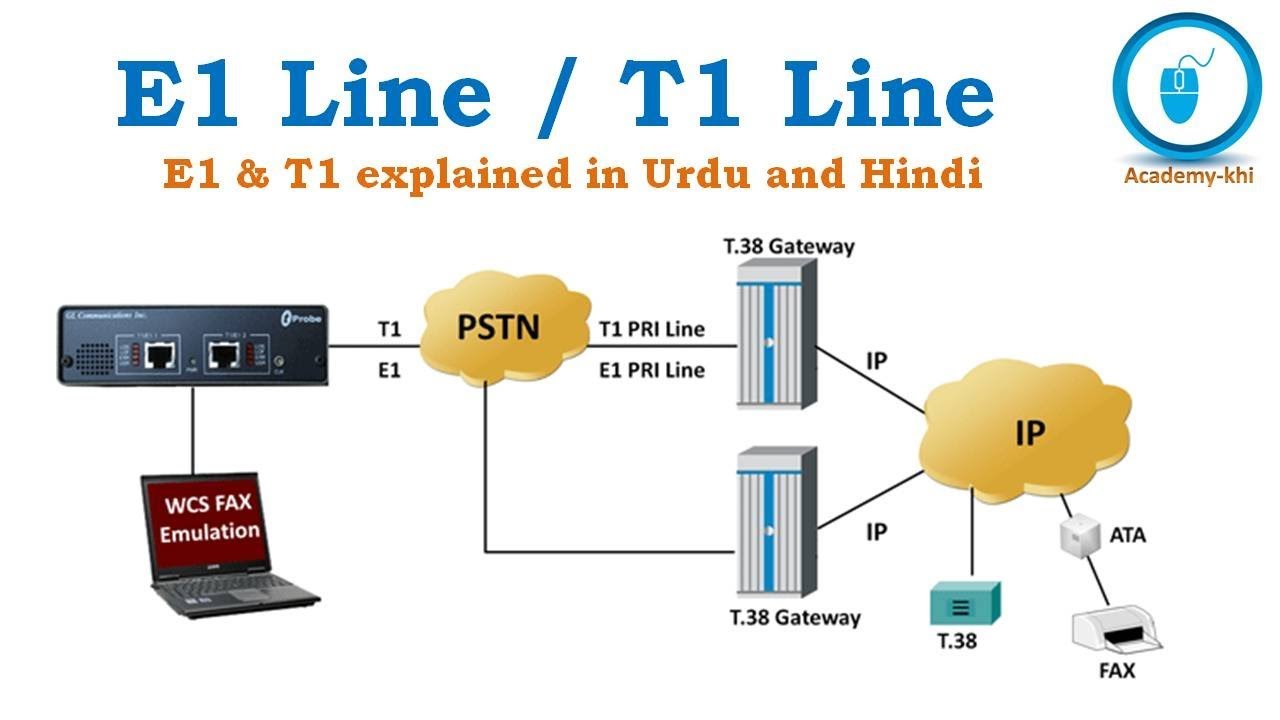
What is E1 line | What is T1 line | E1 and T1 Explained in Urdu and

T1 Crossover Cable Wiring Diagram - Wiring Diagram

T1 basic circuits

Schematic depiction of the switching circuit. T1 and T2 mark the power

CybErtanZ bloG: A Brief About The T1

Basic circuit diagram-T1+T2 PV Surge Protective Device FLP-PV-2P-S